Partnered with #1 ADU Builders
03 Aug
- Golden State Design & Engineering
- Comment 0
What Are Architectural Blueprints: A Complete Guide for California Homeowners and Builders
Architectural blueprints, also known as architecture blueprints, serve as the foundation of any successful construction project in California, from custom homes and ADUs to land subdivisions and small commercial buildings. When clients ask, what are architectural blueprints, they’re referring to a comprehensive set of architectural drawings, construction drawings, technical drawings, and building drawings that visually articulate every detail of a building project. These documents guide the design process, aid in construction cost estimation, ensure compliance with building codes, and support building permits. In this guide, we explain what architectural blueprints are, why they matter, what goes into them, how they’re created, and why you should work with professionals like Golden State Design & Engineering (GSDE) to bring your vision to life.
What Are Architectural Blueprints Today, And Why Do We Still Use the Term?
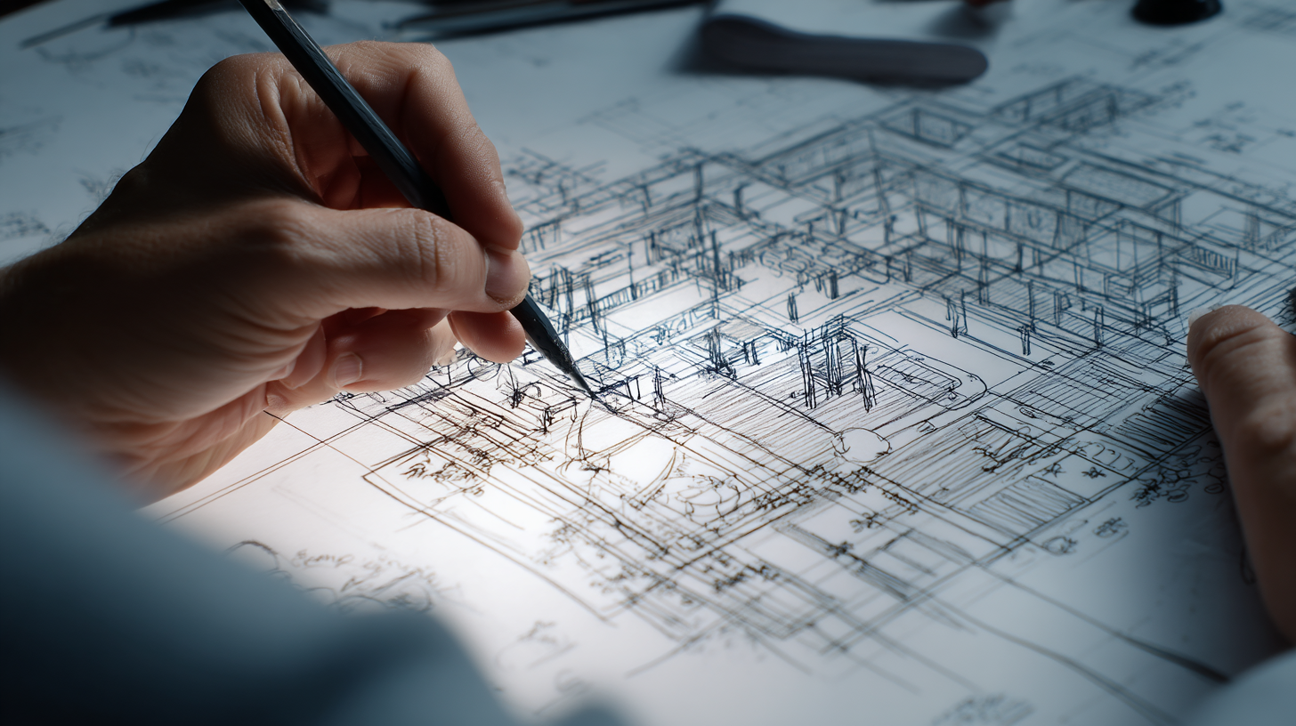
Historically, original paper blueprints featured white lines on a dark blue background, created using a light-sensitive process. Later, whiteprints with blue lines on a white background became more common. Today, architectural blueprints are primarily digital creations produced using computer aided design (CAD) or BIM (Building Information Modeling), yet the term persists. These modern blueprints include large scale drawings that provide detailed drawings with scaled down versions of the structure, depicting architectural elements, structural elements, mechanical systems, plumbing systems, electrical layouts, and more.
In essence, architectural blueprints are technical drawings that communicate detailed information to project stakeholders including architects, engineers, contractors, and permitting officials. They serve as the authoritative reference throughout the building process, from concept through permitting to final construction.
Why Architectural Blueprints Matter
Accurate architecture blueprints are central to the construction process. They facilitate construction cost estimation by detailing materials, finishes, structural transitions, and mechanical, electrical, and plumbing systems. They are essential for building permits, blueprints establish compliance with local building codes, zoning setbacks, and accessibility standards. Without them, a construction project cannot move forward legally or efficiently.
For Homeowners
When you explore building design options, whether for a custom home, ADU, or townhouse, architectural blueprints help you visualize floor plans, elevations, and interior elevations with exact dimensions. They ensure every element, from interior walls and door frames to floor coverings and finishing drawings, is accurately represented. These documents support transparent construction cost estimation and help you understand every phase of the construction process.
For Construction Crews and Contractors
Builders rely on construction drawings to coordinate structural elements including reinforced concrete beams, columns, and foundation details. These maps guide excavation process, installation of mechanical systems, plumbing systems, electrical drawings, and finishing drawings. They keep construction site activities organized, mitigate confusion, and reduce rework.
For Permitting Authorities and Inspectors
Building permits require a full set of technical and construction drawings. That includes site plans, elevation architectural drawings, cross sectional architectural drawings, as‑built drawings (if applicable), and detail drawings. These documents demonstrate adherence to building codes and verify that your project, whether residential or commercial buildings, meets all requirements before and during construction.
What’s Included in a Complete Set of Architectural Blueprints
A full blueprint set includes a variety of drawing types, each playing a specific role:
Floor Plans
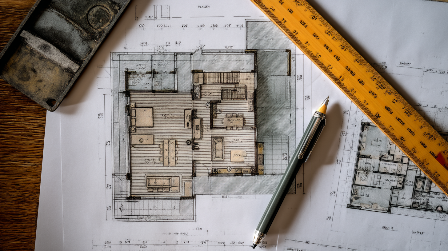
These are large scale drawings of each level, showing architectural elements, interior walls, room layout, doors, windows, detailed measurements, floor coverings, and even furniture placement. Floor plans are key to construction cost estimation and help coordinate different construction elements.
Elevation Architectural Drawings
These drawings depict each exterior face of the building, showing materials, roof pitch, window placement, door frame detail, surface area calculations, and material style. Elevations bring a design’s exterior vision into clear view.
Cross Sectional Architectural Drawings
Cross sections “cut” through the building vertically, revealing structural elements, hidden elements, reinforced concrete beams, inter-floor structural transitions, ceiling heights, and how mechanical systems integrate inside wall cavities.
Site Plans
Site plans show the building in context on the property, including property boundaries, setbacks, driveways, grading, utility connections, landscaping, and access. For land subdivision or new building siting, these technical drawings are indispensable for permitting and construction site layout.
Detail Drawings and Finishing Drawings
Detail drawings zoom in on intricate connections like window flashing, door frames, or construction details at joints. Finishing drawings show final aesthetic materials and transitions, ensuring builders know the exact look and quality required.
Mechanical Drawings, Electrical Drawings, Plumbing Systems
These specialized drawings describe how HVAC, plumbing systems, and electrical or plumbing systems integrate with structure. Electrical layouts show panel locations, wiring routes, lighting fixtures. Mechanical drawings show ductwork and equipment placement.
As-Built Drawings
After construction, as built drawings record changes made during actual building, this updated documentation is crucial for future renovations or maintenance.
Symbols, Legends, and Grid Systems
These include standardized symbols and legends to communicate detailed information clearly, plus grid systems to precisely locate elements across large scale drawings, helping everyone interpret the documents consistently.
How Reinforced Concrete Beams Are Designed, And Why They Matter

Reinforced concrete beams are critical structural elements that support loads across spans. Designing them requires understanding of load combinations, material properties, and code requirements.
According to modern codes like Eurocode 2, designing reinforced concrete beams involves several stages, pre‑design, ultimate limit state, and serviceability limit state, to size beams adequately, determine reinforcement, and control deflection and crack width. Engineering tutorials emphasize calculating loads, verifying bending and shear, and selecting reinforcement, this ensures structural safety and building code compliance. In architectural blueprints, reinforced concrete beams are detailed in both sections and structural elements plans, indicating their size, reinforcement layout, and integration with other construction elements.
The Blueprint Creation Process at GSDE
At GSDE, our design process is structured, collaborative, and rooted in precision:
- Conceptual Design: We start by sketching initial architectural design ideas, mapping the building design, layout, and key architectural elements. This phase includes early construction cost estimation and site analysis.
- Design Development: We refine architectural drawings, integrate structural elements like reinforced concrete beams, mechanical systems, electrical layouts, plumbing systems, and align all details with building codes.
- Construction Documents (CD Set): We deliver the full set of technical drawings, including floor plans, elevation architectural drawings, cross sectional architectural drawings, detail drawings, site plans, mechanical drawings, electrical drawings, plumbing systems, symbols/legends and grid systems, in both digital and printed paper sheets ready for large format copying machines.
- Permit Submission: CDs are formatted for easy submission to building permits authorities across California. We ensure they include building code compliance and site-specific requirements.
- Construction Oversight and As-Built Documentation: We support the construction crew through the build, monitor construction details, and produce as-built drawings to document final outcomes accurately.
Throughout, we may also use traditional tracing techniques for concept layering, translucent tracing paper or drafting film lets us overlay sketches and refine ideas early in the design process.
Tracing paper remains a valuable architectural tool, it’s translucent, allows overlays, and was historically key to creating working drawings before digital reproduction took over.
Why Partner with GSDE for Your Blueprint Needs

Navigating building codes, detailed dimensions, structural transitions, and utility integration is complex. Not all architectural drawings are straightforward to interpret or build from. Mistakes can increase construction cost estimation, delay permits, or compromise safety.
By collaborating with GSDE, you benefit from a fully integrated design process: architectural design, structural engineering, civil engineering, land surveying, and permitting, all aligned in a seamless, collaborative process. We handle everything from site plans and construction drawings to as-built drawings and final documentation, ensuring clarity at every stage.
GSDE’s Blueprint Services
At Golden State Design & Engineering, we deliver blueprint services across California tailored to your project needs:
- Custom home architecture blueprints, including floor plans, elevations, detail drawings
- ADU construction drawings, including plumbing systems, electrical drawings, mechanical drawings
- Multi‑family and commercial building drawings, including structural elements and reinforced concrete beams
- Subdivision site plans mapping property boundaries, grading, excavation process
- Permit‑ready construction drawing sets that ensure building code compliance and support successful permit approvals
- As‑built drawings documenting transitions and hidden elements after construction
Whether your building project is a single custom home, ADU, multi‑unit development, or commercial building, GSDE delivers detailed, precise, code-compliant blueprints that support smooth construction and lasting value.
Frequently Asked What Are Architectural Blueprints Questions
Are architectural blueprints still relevant in modern construction?
Absolutely. Whether digital or printed, architectural blueprints remain essential technical drawings for construction projects, they guide design, building process, permit approval, and construction cost estimation.
What’s the difference between architectural drawings, technical drawings, and construction drawings?
Architectural drawings focus on layout and design, technical drawings include details like electrical layouts and mechanical drawings, and construction drawings are the full set used during construction, including everything from building drawings to site plans.
How are reinforced concrete beams designed and shown in blueprints?
Design follows engineering standards, calculating loads, verifying bending and shear, selecting reinforcement, then detail is shown in cross sectional architectural drawings, structural elements plans, and sections to guide construction.
Do modern blueprints still use blue lines or blue background?
While original paper blueprints used dark blue background or blue lines, modern blueprints are mostly digital. Printed paper sheets may show black lines on white background, blue-line prints are largely obsolete.
Can I sketch with tracing paper during the design process?
Yes. Translucent tracing paper or drafting film is valuable for overlaying sketches, refining design elements, and collaborating with project stakeholders early in design.
Are there building drawings for commercial buildings different than residential?
Yes. Commercial buildings often have more complex mechanical systems, structural elements (like reinforced concrete beams), more stringent building process, and detailed drawings to manage construction site complexity and code compliance.
Conclusion
So, what are architectural blueprints? They are the comprehensive, coordinated set of architecture blueprints and technical drawings that detail every facet of a building project, from floor plans and site plans to cross section drawings, detail drawings, and systems integration. These documents guide your construction process, support cost estimation, enable permit acquisition, and ensure your vision is built with clarity, compliance, and professionalism.
Golden State Design & Engineering is your partner in bringing these blueprints to life. With expertise in architectural design, structural engineering, civil engineering, and permitting, we deliver accurate and buildable blueprint solutions that help you realize your project, on schedule, on code, and on budget. Contact GSDE today to begin your next California construction project with confidence.
#NAICS’s:
- 541310 Architectural Services &
- 541330 Engineering Services
DUNS NO:
- 119132267
#SIC’s
- 8712 Architectural Services &
- 8711 Engineering Services
Cage #
- 9R4L5
#UNSPSC’s:
- 81101500, 81101502, 81101505, 81101508, 81101526, 81101533, 81101522